Bézier curves and 3D modelling
To improve my 3d modeling skills in Blender, I made models for a set of chess pieces. Given their rotational symmetry, I constructed them as traces that Bézier curves leave when they are rotated around an axis.
Chess pieces and rotational symmetry
I chose to make the chess pieces despite not being a great chess fan. They seem to be of an appropriate difficulty level: posing a number of challenges, but well-defined and not too hard.
As the pieces are mostly rotationally symmetric (i.e. look the same when you rotate them by an angle around some axis), I planned to construct them as a curve that’s rotated around an axis. I hoped that repeating this workflow a couple of times with different pieces with an increasing amount of additional work will be a good learning experience.
I started by looking for how people create a rotationally symmetric mesh out of a curve. I found a number of tutorials (1, 2, 3), all of which did only a partial symmetry, i.e. rotated a given mesh by a fixed angle a couple of times.
While technically, as the final model has a fixed number of vertices, its mesh could be created by rotating something by a fixed angle and merging everything, it isn’t the most convenient way to construct it. For example, to change the number of vertices on the circle, I would need to both modify the number of repetitions and the rotation angle.
In the end, I found the screw modifier, which, when set up correctly, was accomplishing exactly what I wanted.
Bezier curves
Once I knew how to rotate a curve to transform it into a surface, I had to learn how to create the curves in the first place.
I used a Bézier curve as a mathematical model for the curve. It is a popular way to express smooth curves in computer graphics.
In theory
A Bezier curve consists of several segments. A single segment is constructed using a number of (at least two) control points. The first and the last control point lie at the ends of the curve, while the remaining ones describe the path the curve takes between them.
Let’s consider a quadratic Bezier curve, i.e. having three (one, apart from the starting and ending ones) control points: \(P_A\), \(P_B\), \(P_C\).
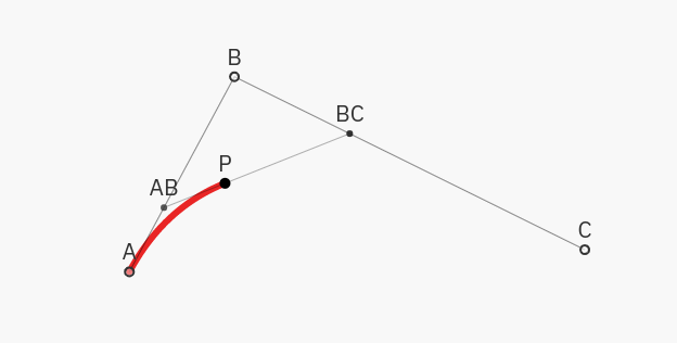
It is natural to express a Bezier curve using a function \(Bez(t)\), which maps \(t \in [0, 1]\) to a point on the curve. It explains how the curve is continuously drawn, starting from the first control point at \(Bez(0) = P_A\) and ending at the last one for \(Bez(1) = P_B\).
The intermediate points are defined as follows:
- Let’s take a point \(P_{AB}\), which lies after \(t\) portion of the way from \(P_A\) to \(P_B\), i.e. \(P_{AB} = tP_A + (1-t)P_B\).
- Analogously, define \(P_{BC}\) on between \(P_B\) and \(P_C\) as: \(P_{BC} = tP_B + (1-t)P_C\).
- Let the point on the curve, \(Bez(t)\) be after \(t\) portion of way between \(P_{AB}\) and \(P_{BC}\), i.e. \(Bez(t) = tP_{AB} + (1-t)P_{BC}\).
If one substituted the definitions of the intermediate points \(P_{AB}\) and \(P_{BC}\), it would become clear that the Bezier curve with three control points is indeed a quadratic polynomial, explaining its name.
The most popular Bezier curves are the cubic ones, that is having four control points. They are constructed iteratively, by first placing points \(P_{AB}\), \(P_{BC}\), and \(P_{CD}\) on the corresponding segments, and then repeating the construction above with the new three points as the control points.
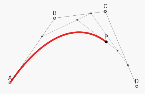
For a deeper (and more interactive) introduction to Bezier curves, I recommend this article by Bartosz Ciechanowski, from where the visualizations above are taken.
In practice
The mathematical formulas above give little intuition on how to place the control points to get a given curve.
To grow this intuition, I played a bezier curve game. One is asked there to create a Bezier curve with as few points as possible to draw more and more complex shapes.
Once back in Blender, after a recommendation from a video, I tried using an add-on for drawing Bezier curves. As I didn’t like its interface, I went back to the default curve-drawing tool.
Process
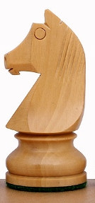
As a reference for modeling the chess pieces, I used this photo of a standard chess set used at tournaments:
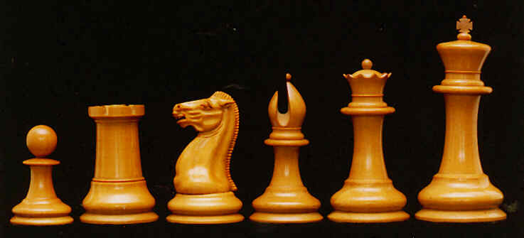
The process for designing various pieces was largely similar:
- I drew the outline of the piece as a Bezier curve. While doing so,
ctrl-RMBwas a useful shortcut for placing new points andvffor making non-smooth connections. - I increased the width of the line to make it more visible at
Object properties > bevel > depth. - I placed an empty on the future rotational axis and parented it to the curve to make moving around easier.
- I used the screw modifier around the empty to create the surface.
- By choosing
overlays > face orientationI checked whether the normals are pointing outwards (blue), and chosenormals > flipif not. - I chose
Object > convert > mesh, as I couldn’t use boolean modifiers otherwise. - I set the bevel depth back to zero
- I cut all the necessary pieces with the boolean modifiers.
- In the end, I checked the geometry for duplicate nodes to merge and applied a subdivision modifier for a more smooth look.
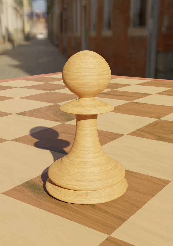
Pawn
I started with the simplest piece to model, a pawn. While making it was just the matter of drawing the curve and rotating it, I was also establishing the process I mentioned above.
Bishop
The next piece I made was a bishop. After doing the rotationally symmetric part, I needed to cut out the hole using a boolean modifier.
Initially, I struggled a little with that, as having the normals the wrong way made the boolean modifier go crazy.
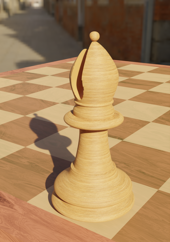
In the final model, you can see edges around the hole that have been smoothed too much. This is an effect of applying the subdivision modifier too early. As I have learned too late, it should be used at the very end, and one should mark the edges which should stay sharp as creases.
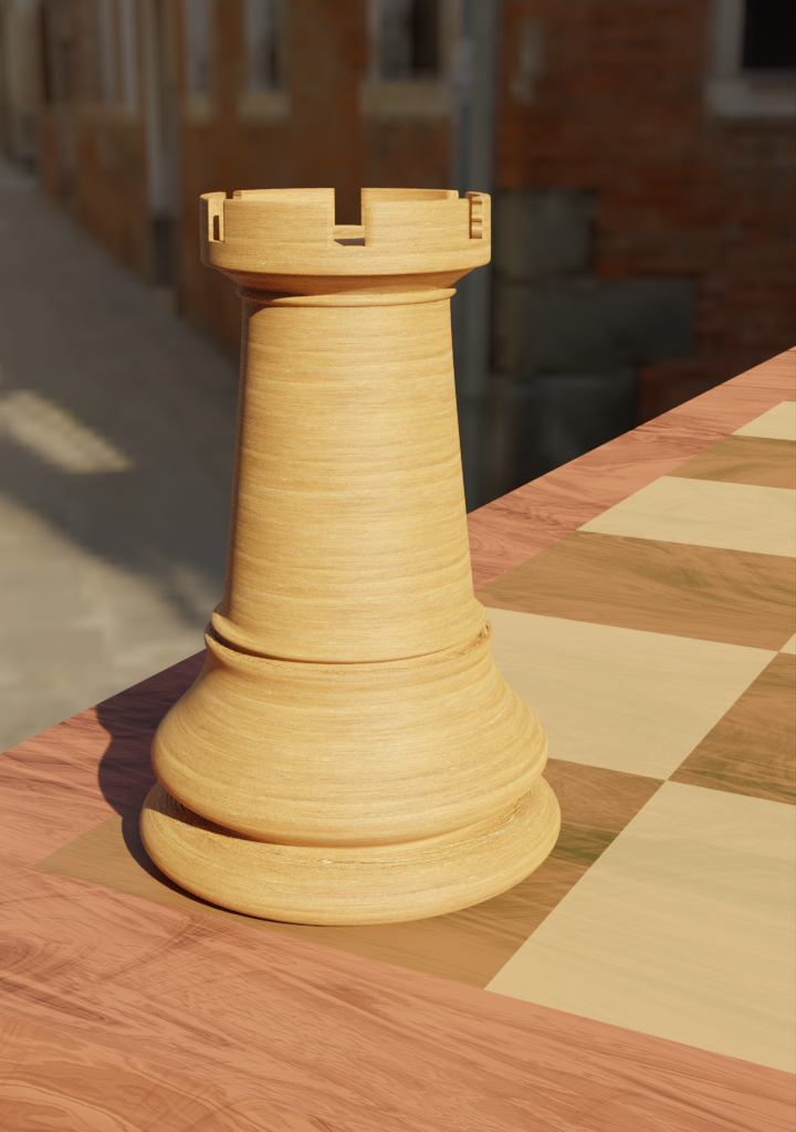
Rook
When I got to the rook, I could use the knowledge from the “partial symmetry with a fixed angle” tutorials I mentioned above: it was easy to make the “holes in the wall”1.
Object offset in Array modifier
One can use the array modifier to do the partial symmetry. To know how to use it with the object offset setting, one needs to understand two types of transformations: in the object mode and in the edit mode.
In the object mode, we are moving/rotating/scaling objects as a whole; every change is reflected in the origin of the object. The transformations are represented (for the whole object) in the Transform panel (and can be later applied to bake in the changes).
In the edit mode, the transformations are performed at the level of vertices, not objects. While it is possible to perform the same transformations as in the object mode, the Transform panel only shows the effect of the location transformation, as, at the vertex level, rotation and scale don’t make sense.
As the transformations are only applied to the particular vertices (and not the whole object), the origin of the object stays put when vertices are edited2.
The transformation that is repeatedly applied to the copied object in the array modifier is the difference between the (object-level) transformation of the offset object and the one being copied.
So, to perform the partial symmetry with the hole in the wall and the empty describing the rotation axis, their transformations need to satisfy:
- location (of the origin) should be the same, as there shouldn’t be any translation between consecutive copies,
- scale should be the same (ideally: 1) too,
- rotation needs to differ by 360 degrees/number of holes (60 degrees, in my case).
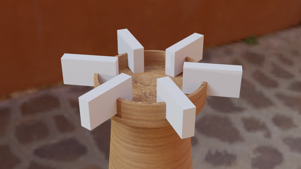
On one hand, I wanted the rotation axis to be outside of the box which represents the hole, to avoid intersecting different holes. On the other, the location of the box needs to be the same as the axis for the consecutive boxes to not move relative to each other.
This is the point where I used the two transformation modes: I kept the box object in the same location as the axis but moved (in edit mode) all the boxes’ vertices away from the axis, to avoid intersections.
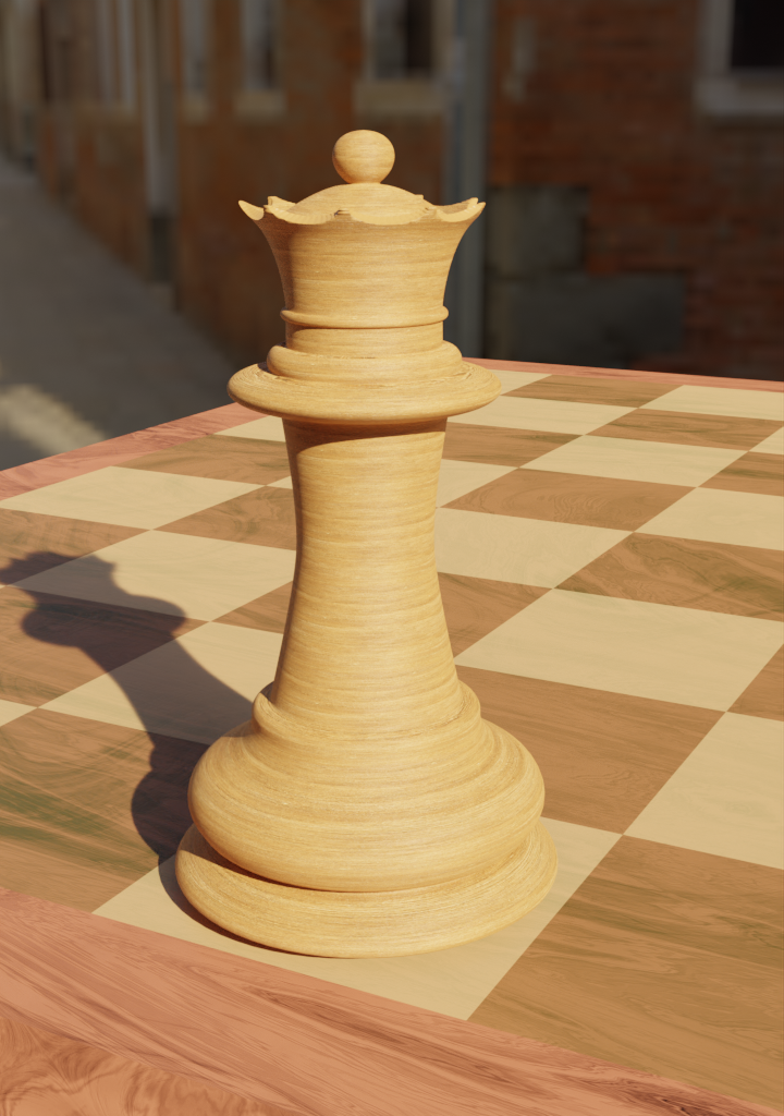
Queen
The queen was more complex than the previous pieces but didn’t involve any new method.
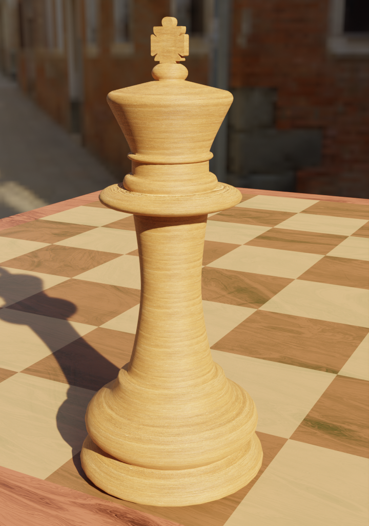
King
For the king, the novel part was the cross on top of its “crown”.
To make it, I drew a separate Bezier curve for its outline, but instead of rotating it, I only mirrored it across the Z-axis.
Then, I converted the curve to a mesh, filled it, and extruded it in the Y direction.
Knight
To make the knight, I needed to follow a completely different process. As it isn’t possible to create it through unions and differences of simple shapes, I borrowed a drawing tablet from my girlfriend and decided to give sculpting a go.
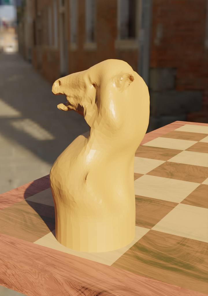
As the first attempt, as you see, was not very successful, I went through a follow-along tutorial on youtube before trying again. The second model was visibly better but still left much to be desired.
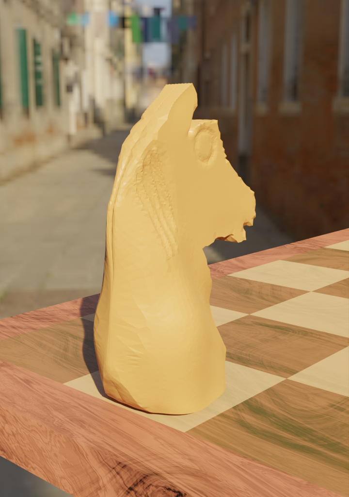
New knight reference
As trying to reproduce that original Stanton knight proved to be prohibitively difficult, I decided to make a different, simpler knight.
I started with making a shape that would smoothly transition from a circle (bottom) to a square (top) with bridge edge loops.
Then, I squished the top to a thin rectangle, while making a proportional edit3 in a non-uniform way, to give the knight the smooth shape of something to be picked by the fingers.
I then proceeded to draw the outline of the knight with a Bezier curve. Similarly to the cross of the king’s crown, I filled and extruded the outline and intersected this horse-like shape with the pawn structure.
Given the number of sharp edges that the final piece has, I made heavy use of creases to avoid them being smoothed out while subdividing.
I then proceeded to cut the holes in the side of the knight. For the eye, I used yet another Bezier curve (now with a bigger bevel) and a boolean modifier.
For the barely-visible cuts marking the horse’s mane, I wanted the curves to taper at their ends. There is a setting for that, which requires passing another object which controls the amount of tapering.
After some trial and error, I established that one needs to draw a graph describing the width of the taper as a taper object. To do that, it was convenient to visualize the local axis of the taper curve by choosing object properties > viewport display > axis.

Board
As a final element to the scene, I made a board to place the pieces on.
I generated the checkerboard pattern with checker texture. To apply it to a part of the model, I made a UV map covering the inner part of the board and applied this texture only there using Texture Coordinate node.
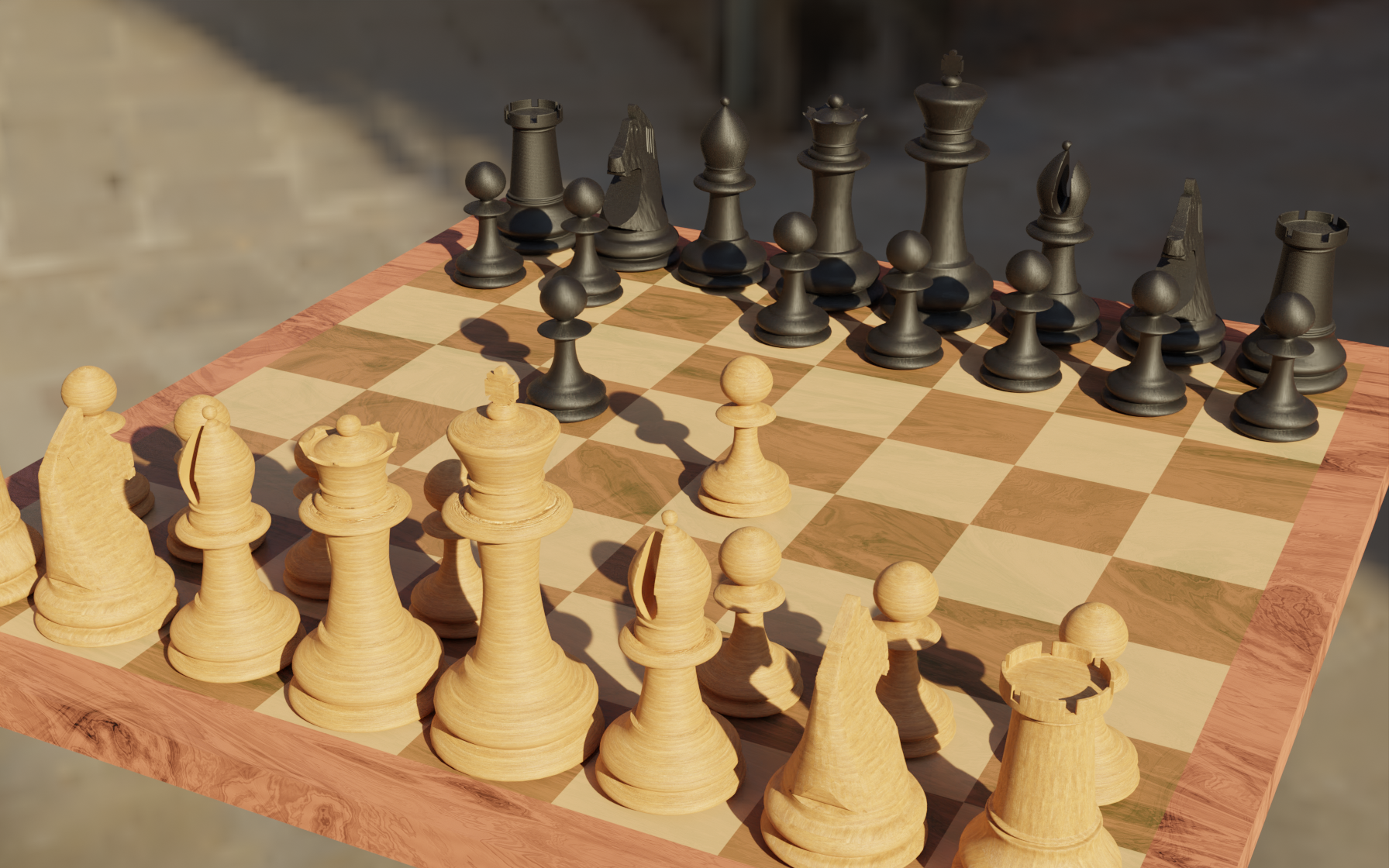
Final render